The HIP consists of a main body, hot field, vacuum system, gas system, gas reservoir, cooling system, control system, monitoring system, hydraulic system, oxygen alarm system and auxiliary systems etc.
The design and manufacture of the equipment should conform to ISO international standards, and its components and instrumentation should all adopt international unit (SI) standards.
The ultra-high-pressure vessel (UHV) part complies with the relevant Chinese standards:
TSG-R0002-2016 "Safety Technical Supervision Regulations for UHV Vessels"
GB150.1~150.4-2011 "Pressure Vessels" and "Design of UHV Vessels"
And it is calibrated to the relevant standards of ASME Boiler and Pressure Vessel Code VIII Book III "High Pressure Vessel Construction Rules".

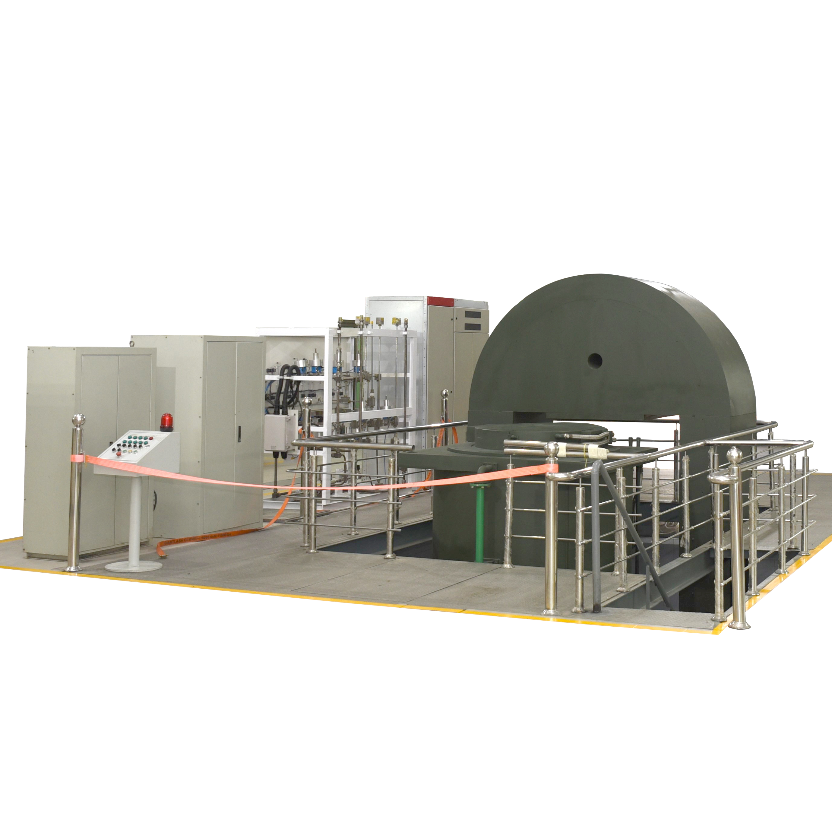
1. Main Body
The main body includes: the UHP vessel (including the pressure-bearing cylinder, end cap and load-bearing movable frame), cylinder support, frame support, guide rail seat, frame driving device, upper plug lifting device, etc.
The design, manufacture, inspection and testing of the UHV vessel are in accordance with the relevant Chinese standards:
TSG-R0002-2005 "Safety Technical Supervision Regulations for UHV Vessels"
GB150.1-150.4-2011 "Pressure Vessels" and "Design of UHV Vessels"
And it is calibrated to the relevant standards of ASME Boiler and Pressure Vessel Code VIII Book III "High Pressure Vessel Construction Rules".
The cylinder body includes: core barrel, water jacket, steel wire, upper plug body and lower plug body, which are made of high strength alloy steel forgings except steel wire. The cylinder body, upper and lower plugs adopt internal water-cooling structure, i.e. the core barrel is equipped with a cooling water jacket for water-cooling inside the cylinder to prevent the core barrel from over-temperature. The main seal adopts a combined sealing structure to ensure no leak inwards when vacuuming and no leak outwards when pressure boosting. The upper and lower plugs can float up and down in order to transfer pressure to the frame and at the same time facilitate frame entry and exit.
Overtravel and positioning block protection is set to ensure safe and reliable movement of the moving parts.
All pressure-bearing parts of the UHP vessel are subjected to 100% non-destructive testing and pressure resistance testing before leaving the factory, and the defect level meets the requirements of the Chinese national standard.
The load-bearing movable frame consists of two semi-circular beams and two columns wound with steel wire, mainly used to bear the axial force transmitted by the upper and lower plug bodies of the UHP Vessel. The columns and half-round beams are made of alloy steel forgings. The frame is hydraulically driven and can travel horizontally on rails.
The frame and upper plug body movement operations are safely interlocked with the gas and heating operations.


2. Hot Field
The hot field consists of: heating assembly, insulation screen (inverted cup type), bottom material table, electrodes, thermocouples, etc.
Heating assembly: side and bottom multi-part heating is used to ensure temperature uniformity. The heating element is made of graphite and is fixed to the barrel support by insulating ceramic parts. The bottom part is set with graphite heating body for heating compensation. Power supply by thyristor regulator with low voltage and high current.
The insulation screen is of multilayer inverted cup type. The innermost layer is a fully sealed inverted cup cylinder with a heat resistant stainless steel protective layer. a low-density insulation layer in the middle. This ensures that gas convection and conduction between the hot and cold zones can be blocked at high temperatures to achieve a good thermal insulation effect.
The bottom material table consists of a material table and a bottom heat insulation pad made of high temperature carbon material, which is extended into the inverted cup to form a heat insulation labyrinth to reduce heat leakage.
The electrodes and thermocouples are plug-in and are guided by positioning pins fixed to the lower plug body. A tungsten rhenium thermocouple is used to control the temperature, and a safety monitoring couple is installed on the outer wall of the thermal insulation layer to ensure safe heating of the equipment.
3. Vacuum System
The vacuum system consists of mechanical pump, vacuum pressure isolation valve, vacuum baffle and exhaust valve, automatic exhaust valve, vacuum sensor, control valve, vacuum pressure gauge, corrugated hose and vacuum pipeline, etc. it is used to vacuum the furnace before pressing.
In the control system, a safety interlock and rapid changeover device for the vacuum and pressure states of the hot isostatic press are arranged to ensure the safety of the vacuum system. The vacuum measurement pipeline and the vacuum pumping pipeline are independent and separate, and there are special measurement pipelines to obtain a more realistic vacuum degree in the reaction vessel.
4. Gas System
The gas system consists of ultra-high pressure compressor, ultra-high pressure valve, high-pressure valve, high-pressure pipeline, ultra-high pressure pipeline, high-pressure pressure gauge, ultra-high pressure gauge, high-pressure pressure sensor, ultra-high pressure pressure sensor, high-pressure rupture disc, ultra-high pressure rupture disc, safety valve, one-way valve, etc., to complete the function of pressurizing and pressure compensation.
An imported ultra-high pressure compressor is selected to meet the requirement that the pressure can be controlled independently at furnace temperature and reach the target of 200MPa.

The ultra-high pressure valves and high pressure valves are made of high quality brand products, including a set of ultra-high pressure automatic valve operating system, to achieve fully automatic pressure control. pressure valve mechanical action has position detection function.
This equipment is equipped with a set of fully automatic gas recovery system. The recovery process is carried out in 3 steps. In the first step, the high pressure stage adopts the pressure balance method, and the gas is discharged directly from the ultra-high pressure vessel to the gas reservoir to control the gas flow. In step 2 the low pressure stage starts the compressor to complete the gas recovery and in step 3 the residual gas is discharged directly.
5. Gas Reservoir
The gas reservoir consists of a gas cylinder array (or high pressure storage tank), high pressure valves, etc. The capacity of the gas store is greater than the capacity of the gas in the furnace at the highest working pressure and highest working temperature to meet the isostatic pressure treatment gas and the process gas in case of emergency.
High-pressure, high-purity inert gases with a purity of not less than 99.999%.
6. Cooling System
The cooling system consists of an internal circulation system, an external circulation system and an emergency system. The heat exchange between the internal and external circulation systems is carried out through a heat exchanger to ensure that the main body does not over-temperature and has high mechanical strength and safety stability.
The cooling water of the internal circulation system is deionised water with anti-rust agent, the water valves and hoses used in the system are made of high quality domestic products, and the water temperature and flow rate are monitored and controlled for a long and reliable working life.
The external circulation system consists of a cooling and heat dissipation device, a power output device and piping valves, etc. The heat dissipation device is installed in an environment with good ventilation and heat dissipation conditions and is connected to the internal water through pipes.
The emergency system consists of a generator (provided by the user) and an ATS automatic conversion device. When the city power supply stops, the generator is automatically switched on by the ATS to ensure that the cooling system, control system and lighting are powered, so as to avoid safety accidents caused by human error.
The external circulation system and the emergency system are provided by the user.
7. Control System
The control system includes temperature control, pressure control, logic control and operating system.
Temperature control mode: Imported temperature controller
The equipment temperature control by programmable imported temperature controller, silicon regulator, thermocouples and other components of the closed-loop control circuit. According to the actual temperature measured by the thermocouple, the corresponding heating output power is automatically regulated to achieve automatic adjustment of PID parameters to ensure the processing quality of the workpiece in the furnace.
Pressure control: evacuation by the vacuum system, vacuum gauge detection, automatic control of the compound vacuum gauge; filling the furnace by the pressure transmitter and electric contact pressure gauge for control.
Logic control method: PLC programmable controller
The logic part of this equipment is centered on the PLC programmable controller, with contactors, relays, air switches, indicator lights and other components. The electrical components are imported brand-name products. All working condition actions are protected by safety chain, and automatic and manual switching operations can be realized.
Operating system
The operating system can adopt the industrial control machine, and the secondary development of the configuration software can realize the human-machine dialogue, all of which can realize the control, monitoring and recording functions of the process, and the user can choose by himself. The industrial control machine is placed in the main control room, and an emergency operation cabinet is set up near the host.
8. Monitoring System
In order to ensure the safe and normal operation of the equipment and personal safety, a number of monitoring probes are installed in the workshop and at the mainframe of the equipment, the gas storage system, the cooling system and the ground pit, and the monitors are placed in the main control room so that the equipment operators can understand the site situation at any time and take timely handling measures.
An oxygen alarm system is set up in the pit. Before entering the pit, personnel must ensure that the oxygen in the pit reaches normal breathing levels. An exhaust ventilation system is set up in the pit (or indoors) to allow for ventilation if the oxygen concentration is too low.
9. Hydraulic System
Including hydraulic station, hydraulic cylinder, valve fittings and other components, mainly for the lifting of the upper plug, the floating of the lower plug and the horizontal movement of the main frame. The system is automatically interlocked with the main frame and the upper furnace cover in place signal system by PLC to avoid misoperation.
10. Oxygen Alarm System
Equipped with oxygen alarm system in gas storage, pit and key operating surface areas to prevent operators from asphyxiation caused by low oxygen concentration, portable oxygen alarm meter should be carried when entering pit, cylinder interior and gas storage for maintenance.
11. Auxiliary System
Auxiliary system includes loading and unloading auxiliary system, special lifting tools for loading and unloading, dismantling tools (special tools for lifting the lower plug, electrode nut locking tools), etc.


 中文
中文